Model -Lenovo G400
Motherboard Number: LA-9632P
Repair Process :
The standby
current reaches 0.045A, which is a bit too high. There should be a leakage
somewhere or the work has occurred in advance.

After removing PU301 and PQ309 and turning on the computer, the problem persisted. Then I disassembled PQ306, PQ307, PQ312, the bridge, BIOS, PQ302, and PQ 303, and the problem remained the same. After repeatedly disassembling and replacing these components, the problem was still not solved.

When blowing the PQ302, I found
120 written on the resistor next to it. The 2 in the middle looked a bit burnt.
When I blew it down, 12 ohms became infinity.
This resistor was not marked
with a circuit number and I didn’t know where it was connected. At that time, I
thought I had found the root cause of the disease. , found a 1 ohm resistor and
connected it.
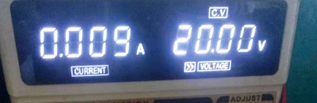
When I turned on the power for maintenance, I seemed to see a small amount of smoke floating in the air, staying for a very short time. But at this time, the standby current of the maintenance power supply is 0.009A. After turning off the power supply and then measuring the resistance of 1 ohm, the value becomes infinity.
There will be 19A. On the other hand, if this logic does not hold true, it means that there is a load on the left end of the resistor, and the load is short-circuited. After careful comparison with the circuit diagram, the identity of the X resistor was finally confirmed.
It turns out that it is PR319, the one in the red circle in the second picture. Then I finally got to the PC314 in the green circle, which is the driver. I blew it down to measure the short circuit. The third picture shows the standby current.
Then I replaced them one by one and used tweezers to short-circuit pins
4 and 8 of JPWRB1. The power-on current came up, and then I slowly restored its
original appearance.

After solving
the problem, review the entire maintenance process. This capacitor should have
a slight standby leakage at the beginning. When the standby current is too
large and does not turn on, it is dynamically triggered.
The state
becomes dynamic large leakage, short circuit protection and does not turn on.
In this state
The change time is very short and cannot be felt. Then during this process
of repeatedly blowing and dismantling components, the high temperature
accelerated his aging and death, and the state became a static short circuit. I
found the final answer after burning the resistor.


No comments:
Post a Comment